
Managing annotation scales
Learn how manage annotation scales and how to keep the size of text items and symbols consistent in the Layout space.- Select one or more AutoRebar entities.
- Run the

EditScalecommand . - Type a new value for the scale (20, 50, 100, ecc) and press Enter.
- Possibly repeat the above operation to find the best fitting annotation scale.
Changing the scale doesn't affect the "physical" dimensions of the Rebars. Only annotations and symbols are scaled to keep the dimension of the characters uniform in the layout, regardless of the layout scale.The Scale tab in the Settings  dialog box can be used to specify a new scale for the entities to be drawn.
The process of scaling an annotation object goes as follows:
- Set the desired units to be used in both the Model Space and the Paper Space. For instance, Meters might be units of choice for the Model Space, whereas the Paper space remains in Millimiters (see also the _PAGESETUP AutoCAD command to set the layout units).
Settings> Units > Model units.Settings> Units > Layout units.
- Decide what size the annotations must assume on paper; for instance, we want the Marks and the bar dimensions to be printed 3 mm and 2 mm high respectively. Set this, or any other values in
Settings> Marks > Marks text height (layout units)Settings> Dimensions > Dimensions text height (layout units)
- Prepare your drawing, possibly using different annotation scales. The annotations will assume different sizes in the model space depending on the scale used for each object. We may use the scale 1:25 for the general view of a beam, while the scale 1:10 might be more appropriate for the sections where the stirrups and the crossties usually involve smaller features.
- Prepare your layout using the _VIEWPORT command. In each viewport, locate the part of the structure you want to represent and run the _ZOOM αXP command, where the α parameter is defined by the following formula:
α = (MU / LU) / Scale

Where:
MU are the Model Units
LU are the Layout Units
Scale is the annotation scale used for the objects shown in the viewport.
For instance, if we were to adopt Meters and Millimeters respectively for the Model Space and the Paper Space, and create a viewport with annotation objects drawn in a 1:25 scale, we would obtain:
α = (Meters / Millimeters) / 25 = 1000 / 25 = 40
while a drawing set in imperial units, with the Model Space in Feet would leads to the following:
α = (Feet / Inches) / scale = 12 / 25 = 0.48.
An arguably faster and more intuitive alternative approach makes use of the Annotative Scale drop down menu and the Edit Scale forms:
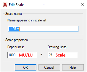
Here, the MU/LU ratio goes into the Paper units field, while the Drawing units fields must be filled with the Scale parameter. That establishes a direct relationship between the model and the paper space units:
MU/LU ∙ Paper units = Scale ∙ Drawing Units.
The standard Edit Scale form and the Annotative Scale drop down menu become essential tools when using AutoCAD  Annotative entities as shown for the SECTION block in the following video.